
Three-Dimensional Foot Position Estimation Based on Footprint Shadow Image Processing and Deep Learning for Smart Trampoline Fitness System
 ,
,
Abstract
:1. Introduction
2. Methods
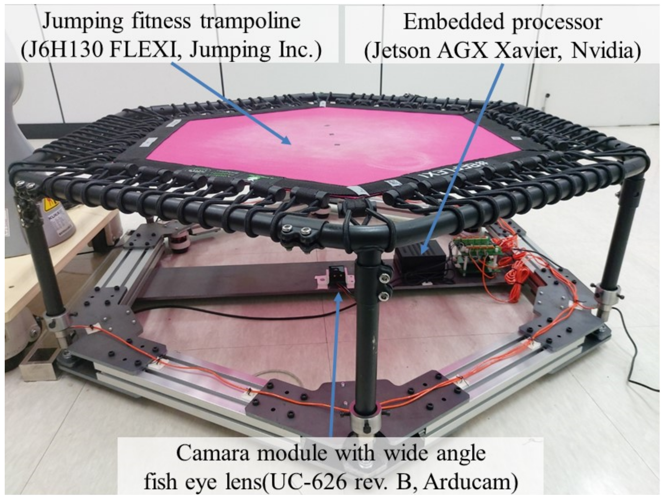
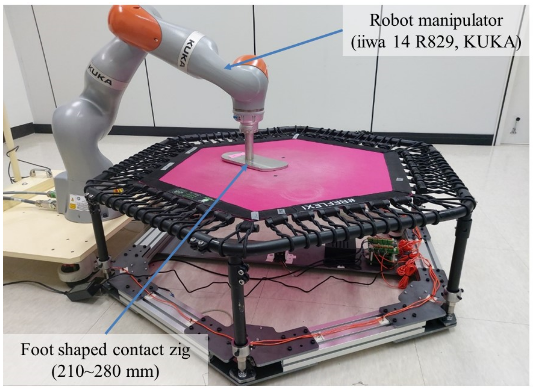
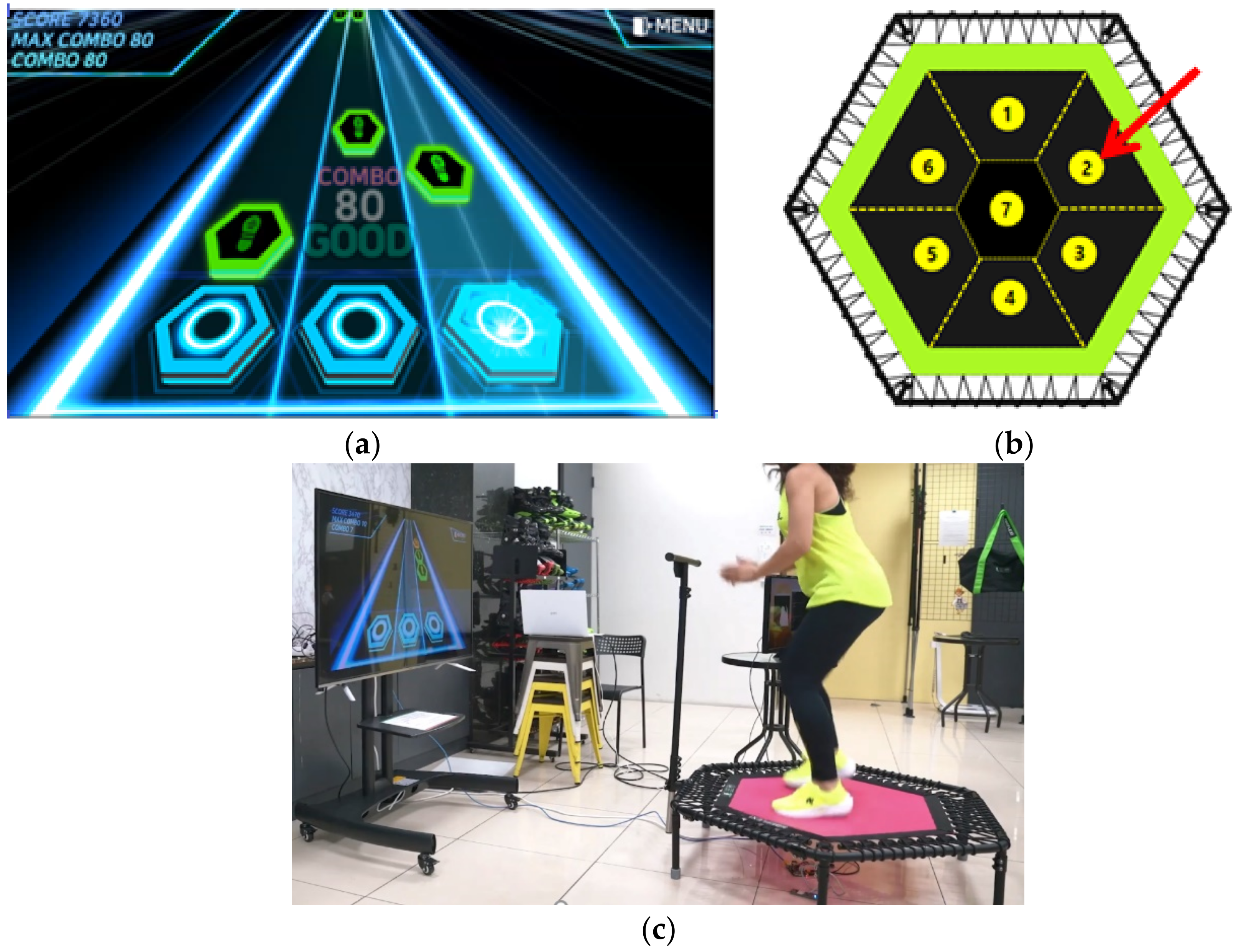
2.1. Overview of a STFS and Experimental Environment
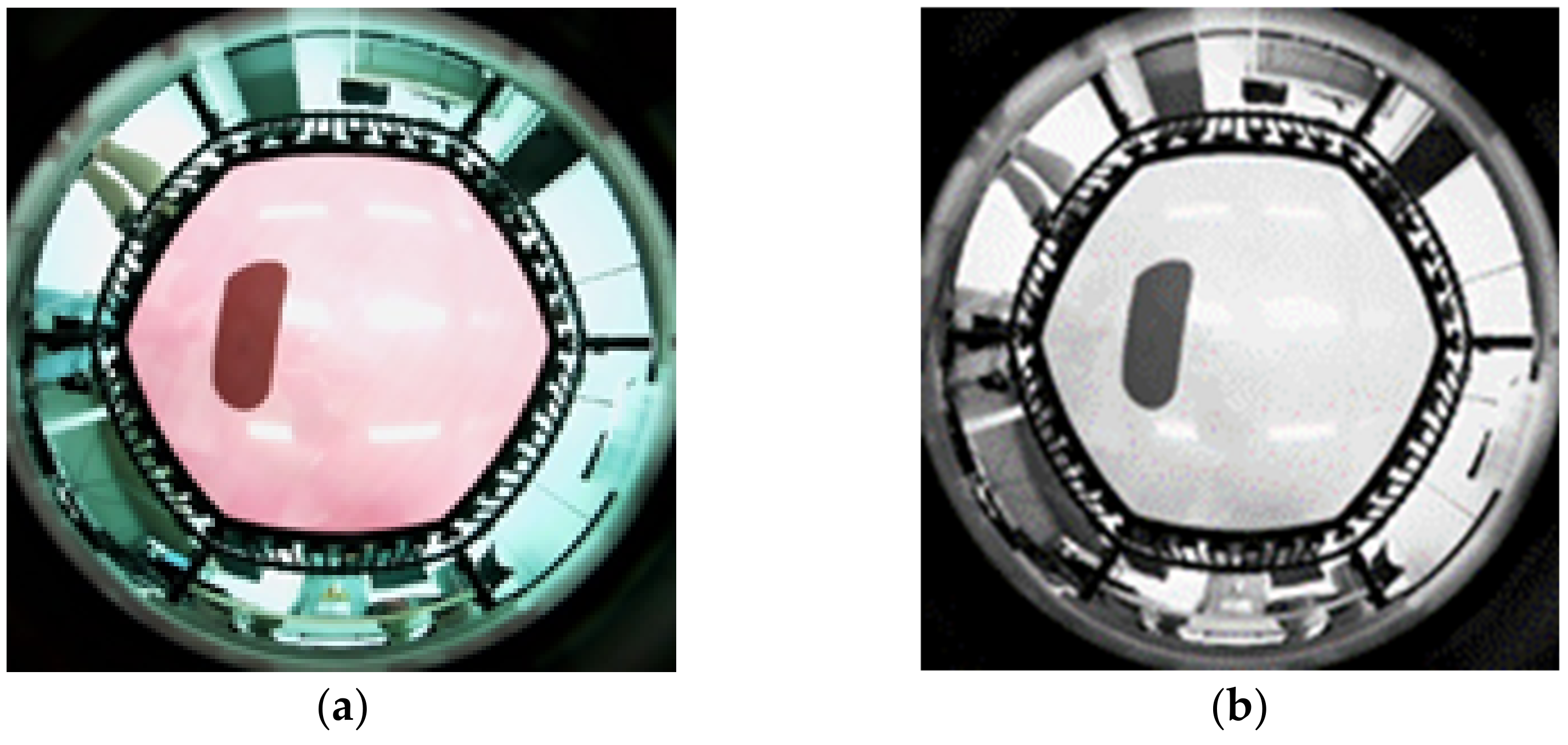
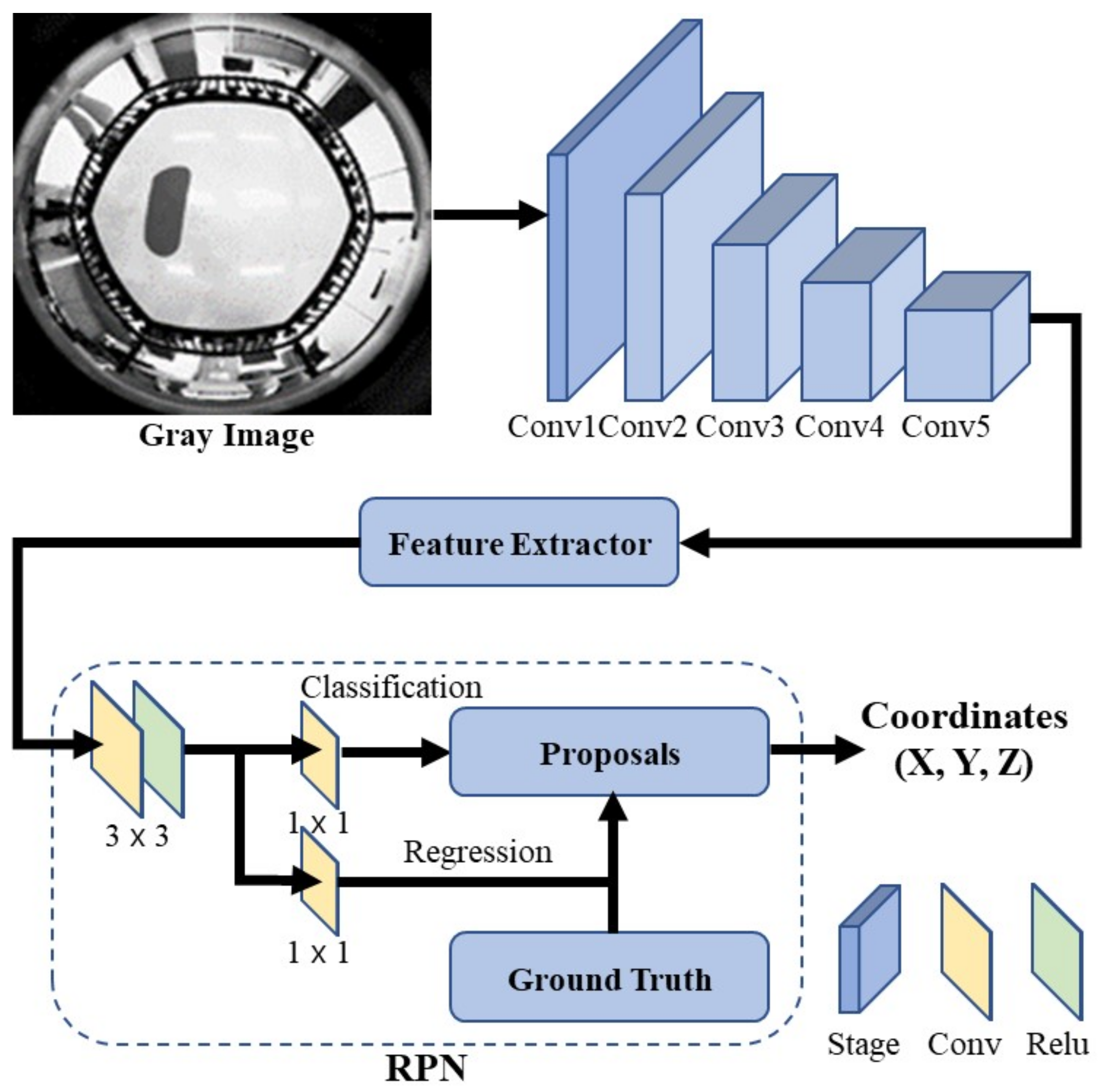
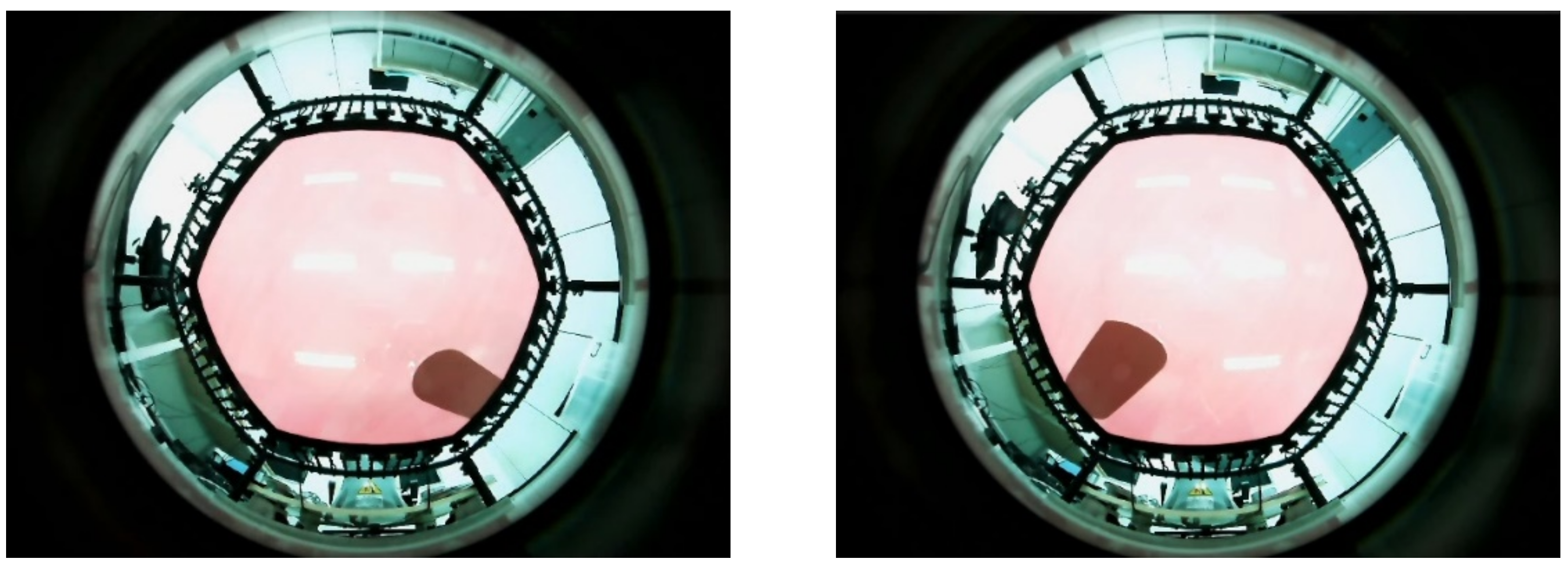
2.2. Network Structure for 3D Foot Position Estimation Based on Deep Learning
2.3. Experimental Method for Data Acquisition
2.4. Statistical Method for System Evaluation
3. Results
4. Discussion
5. Conclusions
Author Contributions
Funding
Institutional Review Board Statement
Informed Consent Statement
Data Availability Statement
Conflicts of Interest
References
- World Health Organization. Available online: https://www.who.int/campaigns/connecting-the-world-to-combat-coronavirus/healthyathome (accessed on 25 August 2022).
- Alonzi, S.; La Torre, A.; Silverstein, M.W. The psychological impact of preexisting mental and physical health conditions during the COVID-19 pandemic. Psychol. Trauma Theory Res. Pract. Policy 2020, 12, S236–S238. [Google Scholar] [CrossRef] [PubMed]
- Rodríguez-Nogueira, Ó.; Leirós-Rodríguez, R.; Benítez-Andrades, J.A.; Álvarez-Álvarez, M.J.; Marqués-Sánchez, P.; Pinto-Carral, A. Musculoskeletal Pain and Teleworking in Times of the COVID-19: Analysis of the Impact on the Workers at Two Spanish Universities. Int. J. Environ. Res. Public Health 2020, 18, 31. [Google Scholar] [CrossRef] [PubMed]
- Peloton. Available online: https://www.onepeloton.com/bike (accessed on 8 August 2022).
- Tonal. Available online: https://www.tonal.com/intelligence (accessed on 8 August 2022).
- Allied Market Research USA. Fitness Equipment Market by Type, End User: Opportunity Analysis and Industry Forecast; Allied Market Research U.S.: Portland, OR, USA, 2019. [Google Scholar]
- Schöffl, I.; Ehrlich, B.; Rottermann, K.; Weigelt, A.; Dittrich, S.; Schöffl, V. Jumping into a Healthier Future: Trampolining for Increasing Physical Activity in Children. Sports Med. Open 2021, 7, 1–7. [Google Scholar] [CrossRef] [PubMed]
- Aalizadeh, B.; Mohammadzadeh, H.; Khazani, A.; Dadras, A. Effect of a trampoline exercise on the anthropometric measures and motor performance of adolescent students. Int. J. Prev. Med. 2016, 7, 91. [Google Scholar] [CrossRef] [PubMed]
- Şahin, G.; Demir, E.; Aydın, H.; Şahin, G.; Demir, E.; Aydın, H. Does mini-trampoline training more effective than running on body weight, body fat, VO2 max and Vertical Jump in Young Men. Int. J. Sports Sci. 2016, 6, 1–5. [Google Scholar]
- Aragão, F.A.; Karamanidis, K.; Vaz, M.A.; Arampatzis, A. Mini-trampoline exercise related to mechanisms of dynamic stability improves the ability to regain balance in elderly. J. Electromyogr. Kinesiol. 2011, 21, 512–518. [Google Scholar] [CrossRef] [PubMed]
- Daneshvar, P.; Ghasemi, G.; Zolaktaf, V.; Karimi, M.T. Comparison of the effect of 8-week rebound therapy-based exercise program and weight-supported exercises on the range of motion, proprioception, and the quality of life in patients with Parkinson’s disease. Int. J. Prev. Med. 2019, 10, 131. [Google Scholar]
- Jumping Fitness. Available online: https://www.jumping-fitness.com (accessed on 6 September 2021).
- Helten, T.; Brock, H.; Müller, M.; Seidel, H.-P.; Mueller, M. Classification of trampoline jumps using inertial sensors. Sports Eng. 2011, 14, 155–164. [Google Scholar] [CrossRef]
- David, E.; Chapman, C.; Bondoc, K. Characterisation of trampoline bounce using acceleration. In Proceedings of the 7th Australasian Congress on Applied Mechanics (ACAM 7), Adelaide, Australia, 9–12 December 2012; The University of Adelaide, North Terrace Campus/National Committee on Applied Mechanics of Engineers Australia, Engineers Australia: Adelaide, Australia, 2012. [Google Scholar]
- Connolly, P.W.; Silvestre, G.C.; Bleakley, C.J. Automated Identification of Trampoline Skills Using Computer Vision Extracted Pose Estimation. In Proceedings of the 2017 Irish Machine Vision and Image Processing Conference (IMVIP), Maynooth, Ireland, 30 August–1 September 2017. [Google Scholar]
- Kazuhito, S.; Mori, H.; Hoshino, J. The trampoline entertainment system for aiding exercise. In Proceedings of the 8th International Conference on Virtual Reality Continuum and Its Applications in Industry, Online, 14 December 2009. [Google Scholar]
- Mori, H.; Shiratori, K.; Fujieda, T.; Hoshino, J.I. Versatile training field: The wellness entertainment system using trampoline interface. In Proceedings of the ACM SIGGRAPH 2009 Emerging Technologies, Online, 3 August 2009. [Google Scholar]
- Raine, K.; Holsti, L.; Hämäläinen, P. Empowering the exercise: A body-controlled trampoline training game. Int. J. Comput. Sci. Sport 2014, 13, 6–23. [Google Scholar]
- Tiator, M.; Köse, O.; Wiche, R.; Geiger, C.; Dorn, F. Trampoline jumping with a head-mounted display in virtual reality entertainment. In Proceedings of the International Conference on Intelligent Technologies for Interactive Entertainment, Funchal, Portugal, 20–22 June 2017; Springer: Cham, Switzerland, 2017. [Google Scholar]
- Park, S.; Park, J.; Ahn, J.; Cho, B.; Lee, S.; Kim, M. Three-dimensional Foot Contact Position on a Smart Fitness Trampoline with a Upward Looking Wide View Imaging System. In Proceedings of the 2021 International Conference on Ubiquitous and Future Networks (ICUFN2021), Jeju Island, Korea, 17–20 August 2021. [Google Scholar]
- Ren, S.; He, K.; Girshick, R.; Sun, J. Faster R-CNN: Towards real-time object detection with region proposal networks. IEEE Trans. Pattern Anal. Mach. Intell. 2016, 39, 1137–1149. [Google Scholar] [CrossRef] [PubMed]
- He, K.; Zhang, X.; Ren, S.; Sun, J. Deep residual learning for image recognition. In Proceedings of the IEEE Conference on Computer Vision and Pattern Recognition, Las Vegas, Nevada, USA, 27–30 June 2016. [Google Scholar]
- Natrup, J.; Bramme, J.; de Lussanet, M.H.; Boström, K.J.; Lappe, M.; Wagner, H. Gaze behavior of trampoline gymnasts during a back tuck somersault. Hum. Mov. Sci. 2020, 70, 102589. [Google Scholar] [CrossRef] [PubMed]
- AAU Trampoline and Tumbling. Trampoline & Tumbling Code of Points; AAU Trampoline and Tumbling: Lake Buena Vista, FL, USA, 2021. [Google Scholar]
- BBC. Available online: https://www.bbc.co.uk/bitesize/guides/zp99j6f/revision/3 (accessed on 25 August 2022).
- Keith, A.; Clement, T.; Draper, N. Developing a mathematical model to predict energy expenditure while bouncing on a trampoline. Eur. J. Sport Sci. 2021, 21, 141–148. [Google Scholar]


| System Type | Pros/Cons | |
|---|---|---|
| Classification of trampoline athletes’ motion using inertial sensors [10]. | Pros | Allows the correct classification of athletes’ movements. |
| Cons | Requires multiple sensors to be installed. Difficult to use for the public as it is designed for athletes. | |
| Characteristic analysis system of trampoline bounce using a high-speed camera and 3-axis accelerometer [11]. | Pros | Effect of bounce characteristics on emotional response can be determined. |
| Cons | No association with exercise and games. Requires a sensor to be attached to the hip. | |
| Classification of trampoline athletes’ motion using a camera [12]. | Pros | Allows the filtering and classification of players’ poses. |
| Cons | Requires secure spacing between the camera and trampoline. Difficult to use for the public as it is designed for athletes. | |
| Analysis of a status and content integrated system using distance sensors [13,14]. | Pros | Increases motivation for exercise through content integration. Available to the public. |
| Cons | Can only classify walking, low jumping, and high jumping. | |
| Jumping game integrated system using Kinect [15]. | Pros | Increases jumping power through content integration. Available to the public. |
| Cons | Requires secure spacing between Kinect and the trampoline. | |
| VR integrated gaming system using a motion-capture camera and HMD [16]. | Pros | Improves the immersion and enjoyment of games. |
| Cons | Requires complex safety equipment. Requires arm and leg sensors and headgear. | |
| Layer_Name | Output_Size | ResNet-50 Layer |
|---|---|---|
| Conv1 | , 64, stride 2 | |
| Conv2_x | , max pool, stride 2 | |
| Conv3_x | ||
| Conv4_x | ||
| Conv5_x | ||
| Average pool, 1000-d fc, SoftMax | ||
| FLOPs |
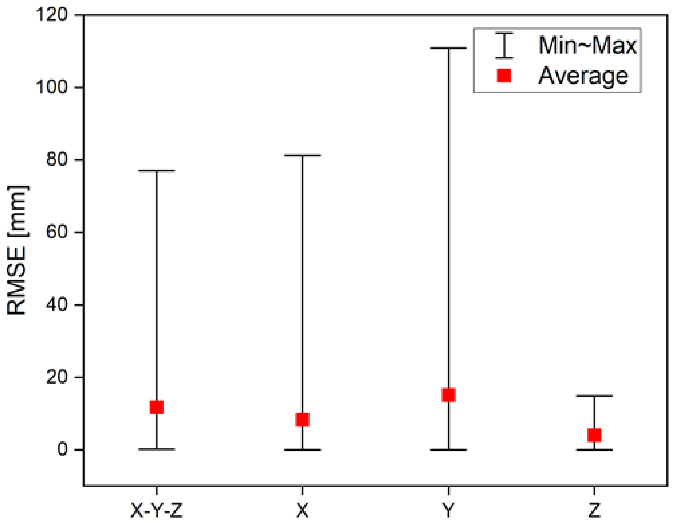
| RMSE [mm] | |||
|---|---|---|---|
| Min | Max | Average | |
| X-Y-Z | 0.2 | 77.1 | 11.7 |
| X | 0.0 | 81.2 | 8.3 |
| Y | 0.0 | 110.9 | 15.1 |
| Z | 0.0 | 14.9 | 4.1 |
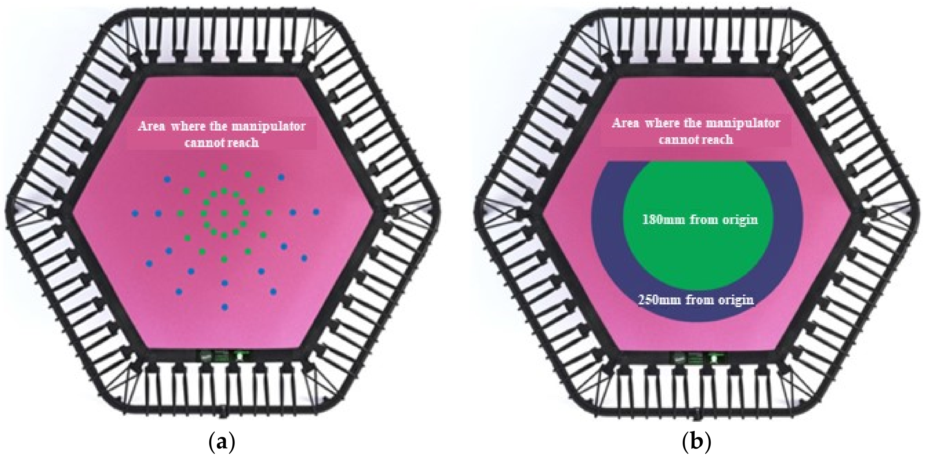
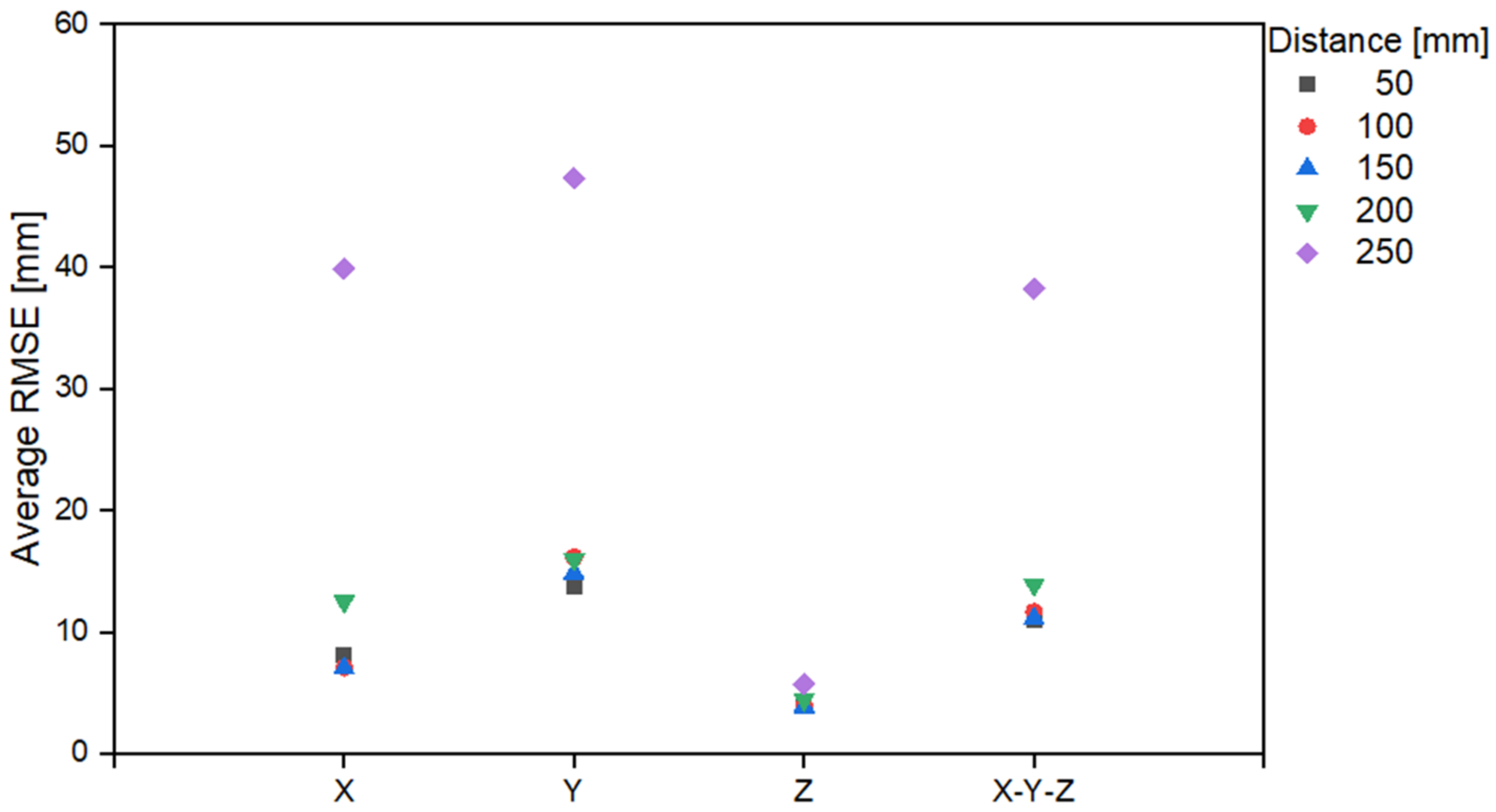
| Area Color | Distance Range [mm] | RMSE [mm] | |||
|---|---|---|---|---|---|
| X | Y | Z | X-Y-Z | ||
| Green | 50 | 8.1 | 13.7 | 4.1 | 11.0 |
| 100 | 7.1 | 16.2 | 4.0 | 11.7 | |
| 150 | 7.0 | 14.8 | 3.9 | 11.1 | |
| Blue | 200 | 12.5 | 16.0 | 4.5 | 13.9 |
| 250 | 39.9 | 47.4 | 5.7 | 38.2 | |
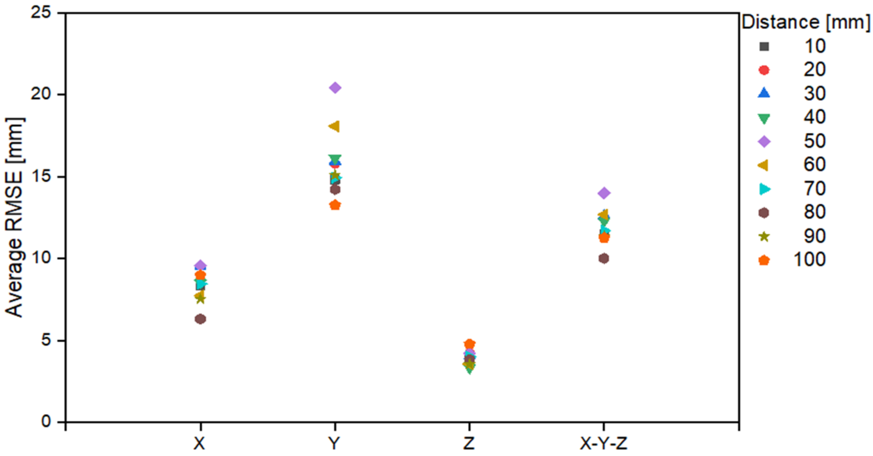
| Depth Range [mm] | RMSE [mm] | |||
|---|---|---|---|---|
| X | Y | Z | X-Y-Z | |
| 10 | 8.4 | 14.8 | 4.0 | 11.5 |
| 20 | 9.0 | 15.8 | 4.2 | 12.5 |
| 30 | 9.6 | 15.9 | 4.1 | 12.6 |
| 40 | 8.5 | 16.1 | 3.4 | 12.3 |
| 50 | 9.6 | 20.4 | 4.2 | 14.0 |
| 60 | 7.8 | 18.1 | 3.6 | 12.7 |
| 70 | 8.5 | 14.9 | 4.0 | 11.7 |
| 80 | 6.3 | 14.2 | 3.9 | 10.0 |
| 90 | 7.5 | 15.1 | 3.6 | 11.4 |
| 100 | 9.0 | 13.3 | 4.8 | 11.3 |
Publisher’s Note: MDPI stays neutral with regard to jurisdictional claims in published maps and institutional affiliations. |
© 2022 by the authors. Licensee MDPI, Basel, Switzerland. This article is an open access article distributed under the terms and conditions of the Creative Commons Attribution (CC BY) license (https://creativecommons.org/licenses/by/4.0/).
Share and Cite
Park, S.-K.; Park, J.-K.; Won, H.-I.; Choi, S.-H.; Kim, C.-H.; Lee, S.; Kim, M.Y. Three-Dimensional Foot Position Estimation Based on Footprint Shadow Image Processing and Deep Learning for Smart Trampoline Fitness System. Sensors 2022, 22, 6922. https://doi.org/10.3390/s22186922
Park S-K, Park J-K, Won H-I, Choi S-H, Kim C-H, Lee S, Kim MY. Three-Dimensional Foot Position Estimation Based on Footprint Shadow Image Processing and Deep Learning for Smart Trampoline Fitness System. Sensors. 2022; 22(18):6922. https://doi.org/10.3390/s22186922
Chicago/Turabian StylePark, Se-Kyung, Jun-Kyu Park, Hong-In Won, Seung-Hwan Choi, Chang-Hyun Kim, Suwoong Lee, and Min Young Kim. 2022. "Three-Dimensional Foot Position Estimation Based on Footprint Shadow Image Processing and Deep Learning for Smart Trampoline Fitness System" Sensors 22, no. 18: 6922. https://doi.org/10.3390/s22186922